Free Energy - Fact or Fiction?
Main Page - Home
Discussion Forum
About This Page
Translate this page
My Research:
-- The Bedini Circuit
---SSG
---Battery
---Trigger Wire
---Coil
---Magnets
---Core
---Tuning
---Attraction Motors
---Repulsive Motors
---Pulse Dis/Charger?
---Slave Coils
---Voltage Regulator
---Generator Wiring
My Projects:
---My 4 Coil Monopole Pulse Motor
---My 12 Coil Monopole Pulse Motor/Gen
---Arduino controlled Bedini Motor and Pulse Charger
---Looping
Other Peoples' Projects:
---Rawbush's Arduino controlled bipolar window motor
DIY Projects:
---Variable Capacitors
Troubleshooting:
---SCR & other uses
---Transistor
---Coil
---555 Timer
---Diode
---Battery
---The Art of Electronics
Experiment Log:
---Setup 1.0- 02/03/2009
----Test data
---Setup 1.1- 03/03/2009
----Test Data -
N/A
Animations:
---My triggering sequence
---John Bedini's Patent Animated 1.1
---3 Coil Lenzless Generator
---Kromrey Generator
---No-Load Generator
Tools and Calculators :
---Coil Calculator
---Flywheel Energy Calculator
---Electric Motor Formulas.
---Tesla Coil Formulas.
---Electricians Toolbox
---Wire Guage Conversions
---Wire Parameter Calculator
---Color Codes Resistor Value
---Misc. Calculators
---Planetary Gear Designer
---Gear Template Generator
---My Epicyclic(Planetary) Gear Calculator
Patent Search Sites:
---Google Patent Search
---U.S. Patent Search
---German Patent Search
---Delphion
---Patents.com
---Canadian Patents Database
---espacenet.com
---freepatentsonline
---European Patent search
---Japan Patent Office
---Auspat
---Pat2pdf.com
---USPTO X-patents
News:
RAWBUSH's Arduino controlled Bi-polar Window Motor Circuit
--- more info - Date: October 02, 2010
Arduino Madness
--- more info - Date: March 25, 2010
This page was last modified on Jan 06, 2013
My private funding in this project has been
tough on me, so when the commodity that we call money ( can you say
"aggregate demand" of the most popular commodity in the consolidated
realm?.... just ask the netherlands about the history of tulips and the
manipulation of prices (what we know as keynesian policy)) ...anyways,
when the parts and tulips become available to be spent for this research
I will proceed building and experimenting. Any new information I come
across in my Pulse Motor/Generator Lab Experiment I will post ,
meanwhile I will be updating and organizing this site with my research
and thoughts on the subject of the concept of my energy machine.
Please come back for updates!
The author may change the information contained here. The schematics, images ,video and my schematic animations are copyrighted by myself. Please advise me if you wish to modify, host or distribute this document and don't make any changes without first consulting me.
To whom may want to try to make a difference on this earth and make a profit, you can't go through the state to achieve it. If one finds a solution to our energy problems and applies for a patent in the federal state. You are binding that technology to the jurisdiction and control of the state. If the state or the usurped state of the monolopolizing energy companies believe that new technology threatens the exitence of the powers that control that jurisdiction, those powers have the right to protect that state, even if it the technology would have been good for mankind in general. The state is not out for the benefit of mankiind, its only for the benefit of the state and its dominion. So before your greed for money consume an idea that you think would benefit mankind, try opening your heart, let your ego down and think about whom you are benefitting with your thoughts and inventions. The last thing a usurped corrupt (government) state wants is mankind to be self-sufficient and in control of your own destiny. This thought alone threatens the fat cats (slave-masters) that feed on their citizens (enfranchised slaves) through taxes, labor and thoughts.
News Flash:
January 06, 2013 -
* I placed a new section of research that you, the
reader can click on for brain food on the subjects of electricty, AC
& DC motors, generators, and other sunbjects on electronics etc. - Recommended Research of Understanding
August 02, 2012 -
* Did you ever wonder how the government controls your life and your wealth?
And did you know its voluntary and you were just in a trance and
conditioned by custom and tradition to comply by it's "operation of
law"?
The images below is alot of research of the most important
subject that every citizen whom is subjected to the social contract or
government should read. Please read a quick essay that I wrote (here) that will get you to the key point of the subject of "voting" an elected sovereign to be a representative to you.
Compartmentalization is how they keep us in the dark under a "veil of ignorance" of the true information to improve our lives on this earth. This diagram I made below is an example of a hidden subject called "Characteristics of Status" and on how they compartmentalize the truth under this veil.

Printable version here .pdf
Edward Mandell House had this to say in a private meeting with Woodrow Wilson (President) [1913-1921]
“[Very] soon, every American will be required to register [state registrar] their biological property in a National system [NVSS - National Vital Statistics System] designed to keep track of the people and that will operate under the ancient system of pledging [borg (borh) & frankpledging]. By such methodology, we can compel people to submit to our agenda, which will affect our security as a chargeback for our fiat paper currency [federal reserve notes]. Every American will be forced to register [Social Security] or suffer not being able to work and earn a living. They will be our chattel [property], and we will hold the security interest over them forever, by operation of the law merchant under the scheme of secured transactions [U.C.C.]. Americans, by unknowingly or unwittingly delivering the bills of lading [entitlements] to us will be rendered bankrupt and insolvent, forever to remain economic slaves through [lex situs] taxation, secured by their pledges. They will [by voting and association] be stripped of their [natural] rights and given a commercial [stock] value designed to make us a profit and they will be non the wiser, for not one man in a million could ever figure our plans and, if by accident one or two would figure it out, we have in our arsenal plausible deniability. After all, this is the only logical way to fund government, by floating liens and debt to the registrants in the form of [Social Security] benefits and [licensed franchise] privileges. This will inevitably reap to us huge profits beyond our wildest expectations and leave every American a contributor or to this fraud which we will call “Social Insurance.” Without realizing it, every American will insure us [by making the people's pledged biological property as surety[ship] by the act of "piercing the corporate veil"] for any loss we may incur and in this manner; every American will unknowingly be our servant, however begrudgingly. The people will become helpless and without any hope for their redemption and, we will employ the high office of the President of our dummy corporation to foment this plot against America.”
The Frankpledge System (1910) - Morris, William Alfredhttp://archive.org/details/frankpledgesyste00morriala

January 17, 2012 -
* I have rebuilt the damage from the rotor failure of my
experiment lab back in September of 2011. It is now up and running
after many months of cobwebs. Also I have other energy machine concepts I
would like to fabricate. One specific idea that needs some attention
from what I have learned from my experiment lab. I will be looking
forward to this next build. I have been engineering this concept in my
thoughts for quite a while now......Be patient and stay tuned in to this
website.........A reminder to my Youtube subscribers. I cannot access
my youtube account for editing and responding to comments. Please don't
waste your time looking for updates there on my progress.
October 7, 2011 -
* I have added some ideas of looping and shuttling the energy in a closed loop system.
September 29, 2011 -
* I have added an animation of Jong-Sok An's patent of his "No-Load Generator" Eliminate and nullify Lenz Law.
September 19, 2011 -
* I have added some new found links in the menu on the left with useful tools, formulas and calculators.
September 16, 2011 -
* I have added some new found links on information about understanding the battery.
* More information found on
Antenna Theory . It may help in understanding your Capacitive, Inductive and Resistance or also known as the "Electrical Reactance" of your RLC (Resistor, Inductor, Capacitor) circuits.
* I have created an animation about my timing sequence in my Experiment Lab.
* I had a succcessful experiment to create a freeduino micro-controlled solid-state "SSG" circuit. I tuned
the best I could before the experiment turned into the dark side of an
experimentors greatest fear of "what is that burning?", but was very
successful as it lasted. I will post the results and schematics and code
when I get a chance.
February 23, 2011 - Attention everyone!...
I woke up today trying to log into youtube and they
have seemed to have had intercourse with google. I cannot access my
account to reply to messages and any of my account changes are
impossible to access. To solve this issue of viewing my subscriptions
and edit my youtube account, and reply to comments that were forwarded
to my private email. It seems that I will be forced to create an
account and register (apply or attach myself) with google.
Unfortunately, I am not too fond of the power and control google seems
to have over our lives for only being a search engine. My issue with
this, is that I am NOT registering to the power trying to consolidate my
online identity into one user-name...not that I have any, but thats not
the point here. The consolidation of power in our world is organizing
in the realm and on the world wide web. Forgive me of my choice to opt
-out of registering my user-name with google, As of today I will have to
leave my youtube channel to gather cobwebs, because I can't access it
with my original registration information, I will have to refuse to be
forced to opt-in to google's request. I guess if you are going to be
looking for updated videos and informationon my progress and ask
questions, you will have to come here to my private webpage where I
control my online channel the way it was meant to be, out of the third
party control of some god-like company to tell me what to do and what
not to do in my life. I guess eventually, they will consolidate
facebook, twitter, yahoo, myspace, and others and control the truth
going in and out of the realm and its technology.
I am sorry everyone -The socialistic walls are closing in fast
and I am going to be sure I don't let the power of google attac[h]k my
identity to someone that controls the gate of information to get in or
out
-- Mark Allen (MAllen7424)
Arduino Madness!
RAWBUSH's Arduino micro-controller running Bi-polar Window Motor
more info - Date: October 02, 2010
A Bedini Pulse Motor and Pulse Radiant Charger controlled by micro-controller
more info - Date: March 25, 2010
About this Page
First off, I am not an Electrical Engineer, and don't claim to have the great knowledge and answers that all of us are looking for. This website is just a representation that I have created to help myself understand this technology of energy machines in a visual way. I may be completely wrong in my visual representation, but it has helped me move forward to understanding the technology that Nikola Tesla, Dr. T. Henry Moray, Edwin V. Gray, John Bedini , Tom Bearden Ph. D and everyone else that has been on-going experimenting and concepts of 'Radiant Energy, alternators, generators, induction motors, permanent magnet motors, and pulse motors etc.
We 'sons and daughters of man' are in troubled times and in my research this energy is there to be ciphoned out. We need to be energy independent from the energy cartels of the metered energy that they make us slaves to.
If any reason Tom Bearden and/or John Bedini don't want this
information posted. Please contact me personally, because I don't trust
anyone after what I found in my research. I have left an opportunity for
guests and readers to comment at the bottom of
the page if anyone has any thoughts or questions to post. Forgive me for
not responding to some comments that I believe are all ready explained
and posted on my webpage. I have no time to repeat myself though I am
all ears to making corrections to the information on this page. Once
again... I am not an Electrical Engineer, I am just a
jack-of-all-tradesman. I am not building this for my own fame and
fortune, I am building this to free myself. And I hope your intentions
are the same. If your looking to get rich by manipulating and
controlling energy technology, then you are the evil that has caused
mankinds descend into the abyss. And good luck getting past the biased
patent office on your way there. Let go of your ego and greed and lets
bring all of mankind back to paradise.
Free yourselves!
Beware:
Researching 'suppressed technology' could leave you angry and lead you
down rabbit holes of truth about the world you reside in and may wake
you up to the nature of reality. You will sift through the truth, lies
and debunkers. You have to take responsibility for yourself in and out
of the realm. Your freedom will not come from a sooth sayer or
comforter. It is your individual responsibility to seek the light to
flee out of the darkness. Question everything!.... and please teach your
children to question it as well.
" Don't always believe what the television tells you."
Do the research!
If you wish to DONATE to this project, due to the economy and circumstances, I can't purchase parts needed to push my research alone please Click here!
Recommended Research of Understanding
- AC MOTORS - Department of Defense 1969
http://www.youtube.com/watch?v=_-WQZ1SGqi4 - AC MOTORS AND GENERATORS - Department of Defense 1961
http://www.youtube.com/watch?v=07uXnc1C5CA - AERODYNAMICS - FORCES ACTING ON AN AIR FOIL - Department of Defense 1957
http://www.youtube.com/watch?v=dY3daNK1Tek - BASIC AMPLIFIERS - Department of Defense 1964
http://www.youtube.com/watch?v=FFAN4nAxkHQ - BASIC TELEPHONY - Department of Defense 1961
http://www.youtube.com/watch?v=oPP-tWXwOFc - CAPACITORS - Department of Defense 1964
http://www.youtube.com/watch?v=xTi6Q0hM3XQ - DC MOTORS AND GENERATORS - Department of Defense 1961
http://www.youtube.com/watch?v=OpL0joqJmqY - ELECTRICITY - INTRODUCTION TO LC OSCILLATORS - Department of Defense
http://www.youtube.com/watch?v=usTmyLlt7iM - ELECTRICITY - VOLTAGE - Department of Defense
http://www.youtube.com/watch?v=b2bt7-7hS_I - PRINCIPLES OF THE STARTING MOTOR - Department of Defense 1957
http://www.youtube.com/watch?v=a_nsgzlrZGU - Principles of Refrigeration
http://www.youtube.com/watch?v=b527al9D_rY - Boilers and Their Operation
http://www.youtube.com/watch?v=kV4s8ugMlUY - TRANSFORMERS - Department of Defense 1965
http://www.youtube.com/watch?v=eZVpufRn3ao - HOW MAGNETS PRODUCE ELECTRICITY - Department of Defense 1954
http://www.youtube.com/watch?v=FehUCQKKRwo - ELECTRICITY - CURRENT - Department of Defense
http://www.youtube.com/watch?v=1zuJBTW0OIs - RESISTANCE - Department of Defense 1974
http://www.youtube.com/watch?v=zYlsqOK5BiY - ELECTRICITY - FILTERS - Department of Defense
http://www.youtube.com/watch?v=51IWqAWPjNI - ELECTRICITY - FILTERS - B - Department of Defense
http://www.youtube.com/watch?v=IkzkqhA9VBw - ELECTRICITY - PARALLEL RESISTIVE CIRCUITS - ANALYSIS - Department of Defense
http://www.youtube.com/watch?v=mei2Ow6v2YY - ELECTRICITY - PARALLEL RESISTIVE CIRCUITS - BRIDGES - Department of Defense
http://www.youtube.com/watch?v=oULmzMvyZxU - ELECTRICITY - PARALLEL RESISTIVE CIRCUITS - POWER-TROUBLESHOOTING - Department of Defense
http://www.youtube.com/watch?v=i-50_U1TJeE - ELECTRICITY - INTRODUCTION TO LC OSCILLATORS - Department of Defense
http://www.youtube.com/watch?v=usTmyLlt7iM - BRIDGE RECTIFIERS - Department of Defense
http://www.youtube.com/watch?v=Y8Lo80UwjO8 - MAGNETIC CORES - PART I - PROPERTIES - Department of Defense 1962
http://www.youtube.com/watch?v=HPT7Wtp3yoo - MAGNETIC CORES - PART II - BASIC CIRCUITS - Department of Defense 1962
http://www.youtube.com/watch?v=An-GIhx0z4c - PLANETARY GEARS, PRINCIPLES OF OPERATION - PART II - MULTIPLE SETS - Department of Defense 1953
http://www.youtube.com/watch?v=rQhzruw2Qh8 - FLUID COUPLING, THE PRINCIPLES OF OPERATION - Department of Defense 1954
http://www.youtube.com/watch?v=leCEmJA0WsI - TROUBLESHOOTING ELECTRIC CIRCUITS - Department of Defense 1968
http://www.youtube.com/watch?v=5ZAya0Zm-NM - CHARACTERISTICS OF CRYSTALS - Department of Defense 1964
http://www.youtube.com/watch?v=CCen81IytsM - SERIES RC CIRCUITS - Department of Defense 1972
http://www.youtube.com/watch?v=t_gxGVJGD5A - CHARGED BODIES - Department of Defense 1984
http://www.youtube.com/watch?v=TCzIWOuTN7Y
The Bedini Circuit
The bedini circuit in my opinion is a very flexible circuit in its simplicity and it uses very few components and with an easy adjustment for 'fine tuning' using a potientiometer and a recommended (analog) (milli-)amperes meter. For the person who is not familiar with the Bedini Circuit, I recommend to build a 'one circuit system', John Bedini's 'Simple School Girl (SSG)' circuit instead of a multi-slave coils circuit system. You can find information about the Bedini 'SSG' anywhere on your favorite internet search engine. You must understand the circuit in its simplicity before wasting valuable time and parts on scaling the circuit. Once you build your first bedini circuit and getting it to run for the first time you will first be surprised how easy it was to build and then after some basic experimenting it begins to open your mind to possibilities that go on endless because you don't see technology like this in our everday life and it opens a fresh newlook in the world of battery charging and motor/generators. Now I can't and I am definately not qualified to get into the physics behind the more advanced bedini circuits. I believe it is all based on 'negative entropy' and how to capture and transform it for practical use. Well enough of the scientific talk lets build a circuit.
The 'Simple School Girl' Circuit (SSG)
The simple school girl circuit is the most basic circuit in the hype of these types of RLC circuits, like a Joule Thief (JT), but with the SSG ...more info about the SSG. John Bedini has put a voltage blocking diode to direct the DC voltage from the pulsed (energizing of the coil) and redirects the BEMF also known as CEMF (Counter Electromotive Force) more info...to a charging battery capturing the energy that is normally wasted in our modern ideas of motors/generators that transformed(energy) into heat. There are explanations of the details to Electrical Engineering(EE) else where on the internet, one being a video called 'Electric Motor Secrets' by: Peter Lindemann. which will explain BEMF in great detail, he also shows you how to make a dynamo-type measuring device for calculating 'Coeffiency of Performance(COP)' and in accuracy horsepower of a motor.
Note: In this presentation I highlight in red recommended information that helped me get started. I decided to share these ideas with you 'the reader' to help you save money in your build and your experimenting. Before I built my first ssg circuit, I spent months researching because of my lack of knowledge of EE and I hope my information here on this website helps shorten your research time. Because I never had any mentor or assistance to help me understand EE and its circuits. I was on my own like a child to comprehend it. I can't build anything that I can't understand how it works and until I can invision it running in my mind. I will not touch a tool to waste my time building it.
... and of course, I am always open to better ways of doing things. Please leave a comment.
The Components:
I don't want to corrupt your belief in your quest but as far as batteries there are many types of, and John Bedini from my research, I believe he likes Interstate batteries, but I have no idea if there is any conflict of interest or debunking there. And from my research and from my experience in building my Experiment lab, I believe in a RLC circuit like Bedini's you are basically tuning an antennae similar to a SWR meter - if you are familiar with CB radios or Ham radio operating equipment, but in this case think of the battery as the antennae (Di-Pole). The circuit needs to be tuned to every different battery because it may either be sulfated or may have different resistance and what needs to be tuned some call this tuning “Impedance matching. ”The Bedini circuit will charge any dead battery, but not all cases every battery comes restored or desulfated to become useable again depending on the condition of the battery. I believe new batteries will give you ideal data to experiment with for better results.
A far as batteries, when you put a load on a battery there are variables of the battery's condition to consider that you may not at first notice on the analog or digital voltage meter. When a dead (absolutely no good and cant light much for too long)battery, even though it may read 12.00v with meter, when you put a 1 Amp load on it how fast does the battery drain to x voltage. A good battery based on a 12volt battery will read on the meter fully charged. ~12.25v to ~13.00v on the meter. A 7amp hour 12 volt battery should run 1 amp for 7 hours at ~12.00 volts not at 11.00 volts, somewhere in there is a variable of a “C20 rate” in the yahoo group forums which is like saying we lied its not 1 amp per hour ,its .350 amp per hour. And when you watch the meter putting a 1 Amp load (this experiment using a 1 Amperes (current) load may be different in your application you are applying) on a good battery the voltage will only drop slightly and stabilize at a voltage then slowly drains, On a bad battery you will see putting a load on it at 1 Amperes, the meter voltage will quickly drop to 11 volts or less ( and this is also assuming the battery you think has its share of time on the standard charger) this sudden fall of voltage is indicating the lead plates in a lead acid battery is sulfated. From research on Bedini's circuit is that he claims his pulse charge thumps the battery with a high voltage spike to vibrate or (ring) the plates to try to desulfate the battery from the shorted out cell or cells (average batteries are made up of cells that hold about 2 volts so assuming the battery you see 6 cells of plates inside of the battery, so you have 6 cells x 2 volts = 12volts) anyways you probably already know that, my point is with a 1 amp load on the battery reading the meter, does the battery reading drop suddenly to 9volts or maybe 4 volts, in the case of the sudden 4 volt drop would indicate you have at least 2 cells that are sulfated and with the 9volt it would indicate at least 4 cells shorting out from sulfating.
Some useful information:
Understanding Surface Charge & Over-all view of a typical Battery System.
- http://www.prestolite.com/pgs_training/training_2.php#top_2
A simple explanation of surface charge (and surface discharge).
- http://www.smartgauge.co.uk/surf_chg.html
Peukert's Equation.
- http://www.smartgauge.co.uk/peukert2.html
more very useful Technical Information on batteries.
- http://www.smartgauge.co.uk/technical1.html
The trigger wire on the coil, in my motors I use 26 guage this is the wire that gets energized as the magnet passes by that generates a voltage onto the base of the transistor which closes the circuit to energize the drive coil (creating the magnetic flux). When the magnet passes away from the trigger coil it disconnects the battery from the drive coil by stopping the flow of electrons using the principles of the transistor as a on/off switch. There are other ways to make a trigger so you dont have to use a trigger coil in your designs, you can also use reed switches(with frequency limitations), mechanical switch(commutators which create fricton) and hall switches(magnteic switches). The choice is yours, its your design use your imagination.
2. The 'Hybrid' Air Coil (The Transformer)
There are many ways to wind the Bedini Coil depending on what you are trying to build. The 'SSG' Coil consists of a 'trigger coil' and a 'drive coil'.The more advanced Bedini coils are relatively all the same except there are extra wires of (Magnet wire) enameled '23' gauge at the same length and the resistance measurement of the wound wires will be different because everyone experimenting cannot make a perfect coil and core because of this, every coil is unique in 'resistance' and 'saturation flux density'. It is also recommended in the forums that the more length of wire the better the results. I have not experimented with those recommendations, but I have tried 2 coils with a 2 different lengths . The coils were trifilar @175ft and trifilar @125ft in length. I definately saw better results from the 450 turn(175ft) lengths.
Questions Gathered :
1. If there are better results with more windings in the coil then how many winds do we have to go for best results?
2. The impedance of free space is 377 ( 376.730313462 ) ohms in the literature of Modern Physics is there a relation to the measured resistance (ohms) in our unique coils? CommentsInteresting Searches:
Scalar Waves
Transverse Electro-Magnetic Wave (TEM Wave)
Displacement Current
Dirac Sea (aka. Fermi Sea)
Splitting The Positives
Negative Entropy
Self Resonance
Negative Resistor
Unified Field Theory
Tesla Switch
Radiant Energy
Sympathetic Vibration
Perpendicular Fields
Zero Back EMF
Self Motoring Effect
Bucking Fields
Scalar Wave Quadrature
Minimal hysterisis
Electrically Resonant
Mechanically Resonant
Bi-filar Windings
Tachyon Tap
Transient Tap
Joule Thief
Casimir Effect
Di-pole-- part 2"If you wish to understand the secrets of the Universe, think of energy, frequency, and vibration." -- Nikola Tesla
The difference between the SSG coil and the more advanced coils:
I have attempted to be invited to the Bedini's advanced yahoo group to understand this technolgy more, but I have never have gotten a responce for my request. Probably because I never followed their instruction in building the SSG with SSG test data. I attempted to request and invitation with data from my 12 pole, which I would say they have a reason for not inviting me. So please understand, I am not a member or have any knowledge of John Bedini's advanced motors unless shared publicly elsewhere in the internet that I may have pointed my internet browser to.
a. The SSG Coil is a 'bifilar coil'...meaning that the SSG coil has two different guage enameled wires of the same length wrappped tightly into 'x' amount of turns. The most common gauges in the search seems to be '23' and '26' guages, eg: take one length of '23' guage enameled wire around 175 feet long and take one '26' guage enameled wire at the same length @175 feet long and wind them on a spool (bobbin) and you have the air coil for a SSG circuit. other combinations of enameled guage wire can be used but it will change resistance values in the finished circuit.
b. The more advanced coils like the one for 'John Bedini's Radiant Energy Powering of the Monopole Motor' and his 'Radiant Pulse Charger' are 'trifilar coils' It is ideally a 1:1 transformer with an optional trigger coil. In laymens terms a 'trifilar coil' is three wires wound onto a spool. 2 wires are exactly the same guage eg: '2x 23 guage enameld wire' @ "x" amount of length (1:1 ratio) and an enameled 'trigger wire' of a smaller gauge eg: '26 guage ' for the triggering part of the circuit also the same "x" amount of length. Only thing really important to pay attention to is... which side is the 'north pole' when pulsed with 'Direct Current' (DC) electricity? ...And finally just make sure the windings are tight on the spool.
c. ...more advanced circuits with slaves are trifilar coils with extra slave coil/wires of "23" guage enameled wire wrapped in addition to the trifilar wrap so now you have a 'quadfilar coil' and again add another slave coil/wires of '23' and keep adding extra wires till your hearts content. Those wires would go to all the radiant energy gathering slave circuit/s just remember to wrap them all together tightly for better induction and results, experimentors even use a drill and twist the wires to make a one twisted cable wire to wrap around their bobbin(spool) @ "x" amount of turns.
Recommended coil to build:
Since I wanted to experiment with several bedini patents I wound my
coils for experimental purposes only. Even though other experimentors
wind as many as they can to a recommended 800 turns according to the
yahoo groups. If you plan on doing alot of experiments in the 'radiant
energy' starting from the most basic setup "SSG" I recommend making a
'quadfilar' coil with 3x '23 guage wires' and one trigger '26 guage
wire' @ 450 turns or 175ft length each. This configuration will leave
the coil open to many different applications and experiments and by
making only one coil it will save you time and money.
1. Transistor x 1 (2n3055)
I Recommend to buy a few for spares.
2. Fast-switching diode x 1 (1n914)
I Recommend buying many for plenty of spares and plenty for other experiments.
3. Resistor x 1 (for this presentation I will use a 680 ohm)
I Recommend to buy an assortment pack with many different resistent values.
4. Rectifying Diode 1000v x 1(1n4007)
I Recommend buying many for plenty of spares and plenty for other experiments.
5. Potientiometer 1k ohm x 1
I Recommend to buy a few for spares.
6. Optional: Doorbell lightbulb (12v 60ma) x 1 ...also known as the "grain of wheat" (helps for visual tuning the Bedini SSG circuit)
I Recommend to buy a few for spares.
7. Ne2 (60 volt Neon Light) x 1 (to protect the transistor in case of accidental disconnects from the charging battery)
NOTE: If you are using a coil for the trigger and accidently disconnect the Charging battery on the SSG
and do not have the Ne2 between the collector and the emitter there
will be a very good chance you will burn out your potentiometer. The Ne2 is there to protect the electronic componants from the high voltage that this unique RLC circuit manifests.
I Recommend to protect each individual transistors at all costs.
8. Magnets- I see everyone using all types of differerent magnets. I chose my grade 5 or 8 ceramic magnets width = 1-7/8(1.875)in. x Depth= 7/8(.875)in x Height=3/8(.375)in. The reason I chose these magnets because they are cheap and you can find them locally at hardware or craft store. My spools are almost the same diameter of the width of my magnets which definately is enough magnetic flux to energize the trigger wire in my coil. I see many people with neodymium magnets with working models but remember the magnet is really only the part of the monopole motor for attracting to the iron core (attraction motor) to create a momentum for the energizing of the trigger coil to apply a voltage to the base of the transistor which opens the gate of energy potential from the battery to the drive wire of the coil. It is the on and off switch of the battery powering the drive coil. I have personally seen experimentors use 1x 1/4 inch ceramic magnets stacked 10 high and embedded in his rotor. He hasn't taken any data down to show me performance, but I did notice if not adjusted correctly in distance from the core it could create unwanted magnetic drag. In all reality the spinning rotor is just a very unique magnetic switch that charges a coil of wire (trigger) that applies voltage to the base of the transistor as an (on/off switch) to allow electrons to flow into the coil.
... ahhhhh but wait!... what about the core? Lets get one thing straight before we go in depth of the core material. The bedini monopole motor is in fact an attraction motor. So if you decide to make a Solid State Radiant Energy Pulse Charger you do not need the core material inside your coil. The rotor with ceramic magnets are attracted to the core (ferrous) material causing the rotor to pick up momentum, when the magnet charges up the trigger coil the power coil will energize acting like an electromagnet with its north pole now cancelling out the magnetic pull and the magnet spins by the core like it was a non-ferrous material then it moves away from the coil and as it moves away from the trigger wire the voltage drops on the base of the transistor and the electromagnet shuts off like a switch. Then the next magnet in motion will atract to the iron core once again repeating the process all over again. If there is not enough resistance on the base of the transistor then the electromagnet coil will push more like a repulsion motor, but this uses more electric current. If too much resistance is applied to the base of the transistor then the rotor will slow down because the electromagnet coil is not creating a strong magnetic flux too cancel out the attraction of the magnet so the results would be a slowing down of the rotor and also the current (amperes) drops down as well. This type of motor in my opinion would not be a very good motor to gain horsepower from, but you can get some very high rpm's from the spinning rotor...of course for every coil you put on adds to its potential. The motor would have to be scaled very large to gain useable torque or horsepower. but if you have a lenzless generator on the shaft. You can have a very effiecient bedini motor spinning a shaft spinning a generator. I have tested these concepts with adding a generator to my bedini motor with good results. With Lenz Law in the way they arent good enough! But you can work your way around lenz law! ... more info.
Understanding the Di-pole, magnetic fields and electric fields
-- part 1 - http://www.youtube.com/watch?v=Xz7PU7QEtAw
-- part 2 - http://www.youtube.com/watch?v=ddU6HBFlvEk&feature=related
The Soft Iron Core and 'The Transformer':
I wanted to figure out how the Bedini coil (The Transformer) worked and the exact geometry and an exact core material to use. The windings are obviously easy but the core material is the essential part of the coil to create attraction of the magnets and maybe the so-called back spike of the BEMF in the monopole motor. Below is what I found and now I understand (I think?) what is needed and now I understand why most of the people are using the R60 welding rods with the copper coating. It may sound too scientific but all the information is right there in the links to help you understand everything you need about the coil and also how standard transformers work.UPDATE: What about the copper coated welding rods in the core?. Well we all know that soft iron as a core creates a stronger electromagnet. I have found that copper in fact will weaken the electromagnet. So I would assume we don't want a strong electromagnet in the SSG because it is in fact not used as a repulsion motor. Therefore a strong electromagnet is not necessary for its functionality, but we do need the soft iron core for its functionality of the attraction of the coming magnet in the SG as an attraction motor. Or maybe it is is for low watt loss, or maybe also "if transformer core is made up of copper the conductivity of copper will be more and hence eddy currents will flow through core therefore eddy current losses will increase", and/or maybe its an ungrounded electrostatic shield aka. faraday shield instead avoiding inhibition of the voltage transients / voltage spikes instead of suppressing them ....your guess is as good as mine.
It seems that the Bedini coil is a hybrid air coil and the core should be made of soft iron of many pieces of thin wire with air gaps for reducing saturation flux density, the result is a reduction in the effective permeability means of the high permeability ('conductivity for magnetic flux') that we need in the core. Materials with high permeabilities include iron and the other ferromagnetic materials. The soft iron wire should be laminated with enamel or poly vinyl acetal, polyester or polyurethane so they create a small hysteresis loop area for low hysteresis loss to get the lowest Remnance for the reason for unwanted eddy current loss amongst the other pieces of soft iron wire within the core. In English I am sure you want to hear... in other words you want the core to let go the magnetic flux fast as possible back to a zero state. Which is where according to Tesla, John Bedini and many other researchers is where the spike originates (the collapse of the magnetic field).
'Soft' magnetic (ferrous) material such as iron alloyed with silicon. Its area is small so it's ideal for a low loss transformer core. The addition of 3 % of silicon to iron reduces the hysteresis loss at 1 tesla from about 250 to 163 J m-3
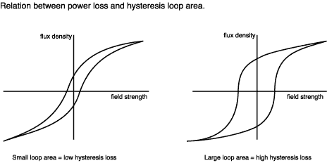
Another ideal core material would be 'Supermalloy' but it is non ferrous so the magnets would never 'attract' to it in the application of the spinning rotor.
References:
http://info.ee.surrey.ac.uk/Workshop/advice/coils/power_loss.html
Other Research reletave to this:
Electrical Reactance
- http://en.wikipedia.org/wiki/Reactance_(electronics)
Tuning
Tuning the bedini circuit is the most difficult thing to do as far as this whole project because their are some variables to concider.
1. Base resistance on the transistor and
2. Distance of coil from rotor(magnets).
3. Bearing friction.
I was fortunate when my first SSG fired right up with a little turn of the potientiometer. With some experimenting I found that there could be multiple sweet spots, but one sweet spot puts your rotor in its highest rpm and the measuring of the current input (running) the bedini circuit is at its lowest amperes (current) value. I classify tuning like catching a wave on a surf board when finding that sweet spot, you will know how much to back off the potientiometer from falling off the wave and when you do fall,you will see changes in the current (amperes meter) readings and rpm's of the rotor is affected. Try to stay on the wave dude!
1. I try not to tune where the coil does not stay singing (self-oscillation), I saturate the coil to self oscillate and back off just until it stops self oscillating, this puts me in a small window where you will fine tune to the sweet spot. From that point I look for the fastest rotor rpm and lowest current. The average current draw to run the SSG I found on a 175 foot coil was about 80-90mA at it's so-called sweet spot.
2. You can use the Grain of wheat 12v 60mA bulb in series with the resistor and the potientiometer and you adjust the potientiometer where the grain of wheat bulb is faintly lit or off. Then from there it puts you in a small window for fine tuning the sweet spot.
3. Adjusting the resistance to find this windows can be very difficult, but you will know when you find it, because as long as friction is not slowing your rotor down you have now tuned your SSG running at its highest rpm and at it's lowest current draw. Now I know this sweet spot is difficult to find with your own unique coil. Try different resistors and modify the resisitor value until you find that set of waves that you want to (surf) or fine tune to the sweet spot. Some experimenters start with a 100 ohm value and work their way up in resistance when they find their coils self oscillating (singing) then they back off until they dont self oscillate and then you have your window for fine tuning your unique sweet spot.
4. Once you find your sweet spot lets mess it up and adjust the distance between the rotor and the coil. Watch the amperes meter, just like the resistance on the base of the transistor it too is a variable in tuning the SSG. Find that sweet spot in the distance from the coil and the rotor as well. The lowest current at the highest rpm.
5. Feeling the resistor for high temperatures could also get you close to that window for fine tuning. The resistor should be at ambient temperature in its window for fine tuning.
6. There are other techniques you can find for tuning on the internet in the http://yahoo.groups.com section. The 1 ohm resistor test they call it there.
Any questions please leave in the comments section.
- Antenna Theory
- http://www.antenna-theory.com/ - Impedence Matching
- http://www.antenna-theory.com/tutorial/smith/smithchart5.php - Electrical reactance
- http://en.wikipedia.org/wiki/Reactance_(electronics) - Resistance
- http://en.wikipedia.org/wiki/Electrical_resistance - Capacitive reactance
- http://en.wikipedia.org/wiki/Electrical_reactance#Capacitive_reactance - Inductive reactance
- http://en.wikipedia.org/wiki/Electrical_reactance#Inductive_reactance - Di-pole
- http://www.youtube.com/watch?v=Xz7PU7QEtAw --
part 2
- http://www.youtube.com/watch?v=ddU6HBFlvEk&feature=related
DIY (Do It Yourself) and Homebrew Stuff
Repulsive Motors & Attraction Motors
The Bedini motor in its glory is an attraction motor. Using the Bedini circuit, when you lower the resistance to the base of the transistor, you are in fact adjusting the "attraction motor" into more of a "repulsive motor". The current draw in a repulsive adjustment is more because you are charging the coil's magnetic field stronger. It GIVES the rotor more TORQUE and OUTPUT POWER. When tuning the resistance to a lower current draw the rotor rpms lower until the point where the coil's magnetic field is not strong enough to cancel out the magnetic attraction between the coil and the magnet which slows the rotor.
When tuned properly you are simply cancelling out the magnetic coupling of the iron core from the attraction of the magnet so the magnet passes cog free from coil and which you lose the torque and the result is that you have a circuit with a unique spinning timing switch that can charge batteries. But don't let this setup stop you from taking advantage of the torque by tuning it into a attractive/repulsive motor and charger. Experiment and you will see for yourself.
When using reed switches, the placement or position of the reed switch also can make the current draw raise or lower and this changing of the variables changes the current draw, speed and torque depending on how much resistance you have on the base of the transistor. You can experiment seeing this effect with a simple coil and rotor with commutator (no bedini circuit) and by adjusting the commutator for timing, you will see the same effect and you will find in this simple setup that spinning the commutator(timing switch) too much either way will reverse the motor the other direction. If you have seen John's first ideas with the motor and generator coupled on a shaft he used a commutator similiar (with or without discharge brush) to what I have mentioned. I believe the EV Gray motor had a commutator setup in the same fashion just more complicated because he used the recovered power to help turn his motor as a repulsive motor.
Bedini Circuit and The Pulse Dis/Charger?
The pulse charger using the bedini circuit is quite simple, you use Magnetic flux induction to capture the 'SSG' charging (harnessed) energy from the pulsed drive coil into a third winding and then rectifying the AC voltage to DC voltage and capturing it in a photo capacitor storing the voltage for use as transformed useable DC energy. But one thing is that you lack is amperes (current) in a pulse charger/motor or pulse motor types alike.
With some experimenting and when the experimentor observes the 'pulse switching' (disconnect/connect from the (SSG setup; It is recommended to use the ne2 on the collector and the emitter of the transistor for protection of a possible high voltage surge) charging battery will charge from a third winding of coil will charge a capacitor to a high voltage and by switching the capacitor to pulse a battery for reconditioning utilizing my guess; about 80-90% of the energy from the system leaving the last 10-20% wasted to run the system. A very efficient battery pulse/charger!
The 'reader' should wonder why is there high voltage when the collector is disconnected from the charging battery with the SSG and how can we capture that high voltage. Now I am not going into the physics here about why there is high voltage. the fact is" it is there" and in another Bedini Patent he has showed us how to capture that potiential of energy using a trifilar coil. Yes the third wire will capture the energy and you rectify it into a capacitor. So now when you disconnect the collector from the charging battery temporarily the high voltage potential has only one way to go and thats through induction of the third winding. Now discharge that capacitor that you have charged up with that potential voltage and pulse a charging battery through a timing switch of your choice either it be mechanical or Solid State. And there you have the basic Bedini Pulse Charger. Tuning and proper timing is a process you can only experiment on your own because your circuit will be unique.
Gathered experiment notes:
Now I have done some experiments with a 450 turn coil with 2x 23guage and 1x 26guage wire and captured its potiential into a 600v 10uf capacitor and found that I was getting up in the 120-300volt range. So I thought well lets put a load on the capacitor while running. I put a few L.E.D.'s on it and they lit up but the problem was that upon applying a load to the capacitor the rotor would slow down drastically. So then I experimented with timed capacitor pulse discharging, which eliminated the rotor slowing down due to Lenz Law the motor/gen was actually running as a motor part of the time and a generator the other part of time. Sound familiar?... from John Bedini's other patents. But because you discharge the capacitor when the circuit is off Lenz Law does not get in the way which means now you can take the capacitor's energy without slowing down the rotor and you can only do it from an external timed switch.
Well, wow I never thought we could bypass Lenz Law! So my mind went into over-drive to experiment in up-scaling the SSG and this Pulsed Captured Energy that I have found to see if I can make a generator/motor with some useable current and also horsepower. And that leads me to the more advanced multi-coil motors and research about them and how to wire them to this idea of creating current from short pulses. And what has given me this idea is from studying windmills and how Permanent Magnet Generators work.
My 4 Coil Monopole Pulse Motor
Now remember I told you that learning the SSG circuit will open your creative mind for useful applications based on what you learned. Well without going too extreme in scaling the bedini monopole motor to a large size I chose to make a 12 coil monopole pulse motor, but I chose to combine alot of applications of EE into one table top project which combines various fields of EE at my disposal to experiment with without building multiple machines. So this project has helped me understand "BEMF Collection, Pulse charging, Battery Charging, Radiant Energy, Generators, Pulse motors, Alternators, Windmill Generators and leaves the door open to combine applications at my disposal for experimentation in a larger scale than just a single SSG circuit... but before I went making a 'my 12 pole' I needed to see if I can create a 4 phase current generator in the like-ness of a three phase Permanent Magnet Generator (PMG) used in a windmills, etc. with this captured pulsed energy for experimenting with and without a timed 4-pole switch. The schematic below is the wiring diagram of my first 4 coil monopole motor that I wired in the older videos of mine.
The (pulse charging) loop was not used in my 4 coil or 3 coil setup videos. The pulse charging loop I started sharing in my later videos during the 12 coil build. I combined the 2 loops into one system for experimentation purposes for easy multiple configurations in one system.
This is the wiring diagram (revision) of my first 4 coil monopole motor
Click schematic to enlarge!

These 4 "Master coils" (I call them Master Coils because these coils are individual trigering/drive coils with its own individual SSG-related circuit) My coils here are 450 turn(175ft) trifilar parallel wound (not twisted). The cores are 3/4(.750)in. diameter. There are 12 magnets on the rotor. The (green) rotor was recycled from a Lexmark laser printer's imaging drum (aluminum) The magnets were taped on with layers of electrical tape. I used skate-board bearings (skateboard bearings are very nice to use they are fast and low friction but they tend to get magnetized and create flat spots on the spinning rotor causing vibration which in turn affects the rpm speed of the pulse motor. The large mass weighs about 6 pounds on a 5/16 shaft.
http://www.youtube.com/v/_-CVdUn9um4&hl=en&fs=1
John Bedini's School Girl Circuit with Slave Coil Information
Each slave coil has each its own transistor and diodes and base resistor (NOTE: Also helps to have identical coils made with the same (resistance) Ohms...good for final tuning). Only thing that is different is that the master coil's base (of transistor) branches off to the base of each slave coil's transistor. Only thing you have to tune is one potientiometer (Remember treat all winds of coils as one coil with its own transistors, diodes and base resistors and the best part ONE POTIENTIOMETER for tuning) running off the same battery and charging the same charging battery/s. Each coil at the same 'x' amount of windings will have to choose the resistance for "YOUR unique coils and your geometry " The geometry of the motor will be a variable in the tuning process.
Example of 1 Master Coil and 2 slave coils setup:
You can also use this information for a quad-filar coil
3 transistors
3 base resistors
3 fast switching 1n914 diodes
3 1000v 1n4007 Diodes
1 1k Potientiometer
1 Primary Battery
1 Charging Battery
Same as school girl just branch off to the other base transistors from the trigger (base of transitor of master coil) the rest is identical to the master coil except without a trigger wire on the slaves because the trigger wire is triggering all three transistor Bases.
Sorry if I repeated myself. Hard to explain but it is real easy. I was confused until I finally just sat down and wired it changing the resistor value until it started running again with all the coils
Remember each coil will have the same base resistor as long as the coil resistance are identical.
My Master and Slave Coils Experiment lab (cross-section)
Here is my experimental setup to create 1 Master (trigger) coil with 2 Slave coils set at 120 degrees apart from each other.
(Success)

http://www.youtube.com/v/j7gTbLhBg5w&hl=en&fs=1
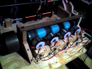
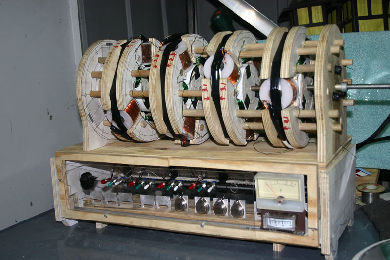
My 12 coil Pulse Monopole/Generator & Radiant Energy Experiment Lab
Most everything I build is all hand made, besides the electronic solid state components purchased from RadioShack.com and Mouser.com. I have hand-wound the tri-filar coils and made my own iron cores from soft iron tie-wire purchased at local hardware store. Its not a clean, balanced machine, but it has moved me forward in experimenting.
My Goal with this prototype or whatever you may want to classify it as is to build a lab test unit with multiple functions in teaching myself for experimentation into the technology of Windmills, Generators, Alternators and Radiant Energy all in one unit. Sounds far fetched and crazy, but all I can say is...over a year ago I didn't care less how all this stuff works and if a hobby don't stimulate the mind what motivation will push you to advance.
http://www.youtube.com/v/TaQPg50l0n8&hl=en&fs=1
http://www.youtube.com/v/FQt5YTCjD0U&hl=en&fs=1
Above picture taken : 12/19/2008

Above pictures taken : 12/31/2008
January 16, 2009 - February 10, 2009 Test run data :
Above picture taken : February 20, 2009
http://www.youtube.com/v/R6RczHqbAX0&hl=en&fs=1
Generator Wiring
Delta and Wye(star)
3 Phase -
AC to DC
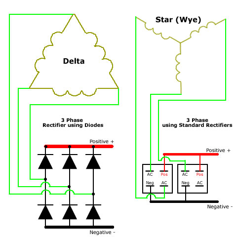
My (4 phase) green coils(generator coils) are 22 guage magnets wire at 136ft. in length, I took an Ohm reading of each coil which read 1.3ohms each and the measurement of three in series at 2.3 ohms. I have had many configurations in this generator that gave me multiple voltage outputs including Star, Delta and other methods that required storing the collected power. I use this generator for many experiments including:
1. Generate power back in the primary battery for longer lasting run time. (very efficient motor)
2. Charge other bank of batteries.
3. Charge Capacitors.
4. Load up some lights .
5. For insightful and unsuccesful self-running experiments.
http://www.youtube.com/v/SIxttB6jxpc?fs=1&hl=en_US
More References to Generators, Alternators and Magnetos:
1. UNDERSTANDING HOW GENERATORS WORK
- http://www.anoldman.com/modules.php?name=Articles&page=generator.html
2. What is the effect of running coil connections parallel to each other?
- http://www.fieldlines.com/board/index.php?action=printpage;topic=140932.0
3. Wind Generator - Star Delta Controller
- http://www.electro-tech-online.com/alternative-energy/30160-wind-generator-star-delta-controller.html
Looping
I have done some experiments of capturing the BEMF and shuttling it back to the primary battery. I have learned from countless hours to see what can be achieved by this setup. I have learned that this setup just makes a very efficient spinning rotor. Of course, depending on its geometry and size to make this spinning rotor do any useful work it will have to be many coils to get enough horse-power to turn maybe a lenzless generator or similiar to charge a bank of batteries with no-load. This setup of looping only uses the excess energy captured to push the circuit to run with more potential using up the energy with the end result of longer run times and time staring at a voltage meter to find out it will never gain and always drop.
But I did not give up there. Now I am still on-going with the idea of looping the energy back to the primary. This setup will require some sort of voltage regulator to keep the SSG running at a fixed voltage and still be able to have the potential to charge the primary battery. Past experiments have convinced me that I have achieved to charge my 12 volt batteries while running a SSG circuit at a regulated voltage of 6 volts. I have a video of this experiment here. These experiments are on going and I do not have any conclusions of the results in the attempt to eliminate battery swapping. Alot more to come in this subject in
DIY Regulator circuit.
- http://www.youtube.com/watch?v=GSzVs7_aW-Y
I know everybody wants fast results and factual data to satisfy your mind's endless questions. I just have to say that building this project opened up endless of possible experiments that should have been taken in depth during the build, but if I would have stopped and experimented at every possible level, in experimenting it takes time and preperation to setup for a controlled experiment. It is obvious that I am also a backyard builder. My problem in the build was if I was going to scale it up to 12 coils how would I do it and what did I want to build. Well what I wanted to build wasn't an option because of the cost. But if any of my friends know me. I wanted to build everything. And I like building unique things. I wanted to build a windmill in the begining which I may still do and/or generator and spend time building and researching this Radiant Energy. Well I spent months with small experiments with the Radiant Energy experiments but it wasn't to take data down, I just wanted to scale the circuit for now to 12 coils to see if there was any torque or horsepower gain in scaling it up in size.
Experiment log:
These experiments are based on my geometry of motor and design of my control box. They are notes to myself... please dont take out of context. Your results in same experiment may differ from your designs and wiring.
SSG Mode: Energy captured from the collector of the transistor.
Induction Mode:
Energy collected from inductance through third wire (trifilar) on the
coil to a capacitor bank for storage. Bedini Patent Configuration
bypassing pulse...Taking the stored energy directly from the capacitors.
Pulse Mode (Mechanical Switching): Bedini Patent configuration.
in my geometry and design in a syncronized 4 phase synchronized pulse
to discharge the capacitors with the Bedini SCR discharge circuit of the
capacitors
Setup 1.0:
12 coils driving motor:
SSG Mode - 12 coils charging battery in SSG
configuration with only 4 coils (masters) capturing BEMF through
induction charging caps (in this experiment used to light up 20 watt
bulb).
Induction Mode - 4 coils BEMF into capacitors and
stored/used (in this experiment used to light up 20 watt bulb) & 8
coils Charging battery (SSG configuration) Pulse mode configuration with
60v neon bulb on base for trigger.
-
Experiment 1 - February 26, 2009 ---- Four
trigger coils wired to photo flash capacitors in a 4 phase arrangement
in parallel for current. Input about 6 watts (4 coils) ...all other (8)
coils running charging Battery in SSG configuration). Experiment based on only 4 coils only.
- In 'SSG mode' (still charging battery) lights up a MR-11 12 Volt halogen brightly (actual watts not measured) running from induction. Adding more load will cause motor to slow down due to Lenz Law.
- Lights up the bulb brightly in 2 positions 'SSG mode' (still charging battery) and 'Induction mode (not charging battery lighting the light through induction of the coils)' bypassing pulse for steady current. Instant lights on when capacitors charge up. Adding more load will cause motor to slow down due to Lenz Law.
- Discharge switch discharging wired capacitors in parallel 4 pulses per revolution. Runs well but not bright as Experiment 1 with MR-11 12 Volt halogen bulb but the faster it goes the dimmer the light. The slower it goes the brighter the light gets. Adding more load will cause motor to slow down due to Lenz Law.
Note: Lenz Law is in the way!
Experiment 2 - February 26, 2009 ---- Four trigger coils wired (induction) to photo flash capacitors in parallel in a 4 phase arrangement for current. Input about 6 watts (4 coils) ...all other (8) coils running charging Battery (Input about 20 Watts) in SSG configuration). Experiment based on only 4 coils only.
Note: The more pulses per revolution in the coil which causes the capacitors to charge higher) lots of flickering from the lack of speed of the motor.
Experiment 3 - February 26, 2009 ---- Four trigger coils wired (induction) to photo flash capacitors in a 4 phase arrangement for current. Input about 6 watts (4 coils) ...all other (8) coils running charging Battery (Input about 20 Watts) in SSG configuration). Capacitors discharged through a switch one pulse per revolution 30 degrees after master (trigger coil) has turned off. Experiment based on only 4 coils only.
- In 'SSG mode' lights up not as bright as Experiment 1 MR-11 12 Volt halogen (actual watts not measured) running from induction. Adding more load will cause motor to slow down due to Lenz Law. SSG mode the bulb is not as bright as the earlier Experiment 1 needs to pick up speed. Adding more load will cause motor to slow down due to Lenz Law.
- In 'Induction mode' (induction) with switch discharging capacitors individually in a 4 phase configuration. Each capacitor discharges one pulse per revolution. The light goes as bright as other experiment 2, but 'Lenz Law' has been bypassed and the motor speeds up upon the applied load.
Note: The slower the motor the more pulses per revolution in the coil which causes the capacitors to charge higher. The faster the motor less flickering of the light.
Voltage (Multiplier) doubler circuit test notes:
Experiment 4 - February 28, 2009 ---- Four trigger coils wired to photo flash capacitors in a 4 phase Voltage (Multiplier) doubler circuit arrangement in parallel for current. Input about 6 watts (4 coils) ...all other (8) coils running charging Battery (Input about 20 Watts) in SSG configuration). Experiment based on only 4 coils only.
- In 'SSG mode' (still charging battery) lights up a MR-11 12 Volt halogen (actual watts not measured) running from induction. Adding more load will cause motor to slow down due to Lenz Law. the light amperes doesn't come close to Experiment 1.
- Lights up the bulb but very dim and slows to the motor to almost stop in 2 positions 'SSG mode' (still charging battery) and 'Induction mode (not charging battery lighting the light through induction of the coils)' bypassing pulse switching circuit for steady current. . Adding more load will cause motor to slow down or stop due to Lenz Law.
Note: Gave higher voltage but adding load gave poor results compared to the earlier experiments. I will be changing back to my normal 4 x 1n4007 bridge rectifiers eliminating the Voltage (Multiplier) doubler circuit for now.
Setup 1.1:
12 coils driving motor:
SSG Mode - 12 coils charging battery in SSG configuration with only 12 coils (masters) capturing BEMF through induction charging caps (in this experiment used to light up 2 20 watt bulbs).
Pulse Mode - 12 coils BEMF into capacitors and stored/used (in this experiment used to light up 2 20 watt bulbs)Experiment 5 - March 3, 2009 ---- Four trigger coils and 8 slave coils wired to a series of photo flash capacitors in a 4 phase arrangement in parallel for current. Input about 26 watts (12 coils)
- In 'SSG mode' (still charging battery) lights up 2 MR-11 12 Volt halogen (actual watts not measured) running from induction. Adding more load will cause motor to slow down due to Lenz Law. see 'video 1'
- In 'Pulse mode' (induction) with mechanical switch discharging sets of capacitors individually in a 4 phase configuration. Each set of capacitors discharges one pulse per revolution. The 2 lights MR-11 12 Volt halogen (actual watts not measured) running from induction now goes as bright as experiment 1, but 'Lenz Law' has been bypassed and the motor speeds up upon the applied load. see 'video 2'
Note: I noticed when in 'Pulse mode' the lights are brighter with less amperes. In Experiment 1 one 20 watt light consumed 1.00A. in Experiment 5 the 2 20 watt lights only consumed 350mA with the same brightness.
http://www.youtube.com/v/8lwUHO7FyL8&hl=en&fs=1
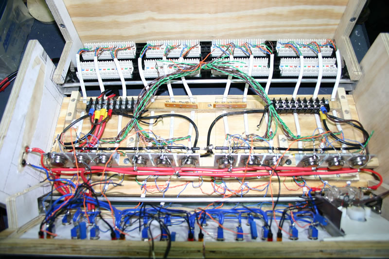
Control Box Upgrade
Sept. 30,2009... in progress


These new boards gave me alot of upgrade room. I am sortof satisfied
with the goal I set out here in making space. The disadvantage of this
upgrade is because I handmade these boards. Test running resulted in
different meter readings amongst each board unlike my first set up of my
control box. I kinda regret not making the box
bigger and just leaving everything the way I first set it up and added
the additional radiant circuits to finish off this updated control box.
This result convinced me that every wire must be precisely the same size
to have multiple coils to match the others for tuning and performance.
One day when there is time I will most likely resolve the mismatch by
rebuilding everything again the same way as before but the control box
will have to have more volume of space to complete what I have in
thought.
6 Volt Battery Charging a 12 Volt Battery Test
http://www.youtube.com/v/Lc-utBpQrIU&hl=en&fs=1&
http://www.youtube.com/v/tMlwTRJZU-E&hl=en_US&fs=1&
http://www.youtube.com/v/kqH7WWpVhCk&hl=en_US&fs=1&
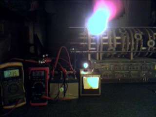
Freeduino micro-controller meets my monopole pulse motor/generator Experiment Lab
http://www.youtube.com/v/-AnLMotPUf0&hl=en_US&fs=1&
My arduino Clone aka Freeduino is now controlling my motor and discharging capacitors to charge batteries.
John Bedini Patent Animated
"Click Animation speeds below for a more detailed image
...Be patient for animations to load."
Animation Speed : Fastest 120fps | Faster 62fps | Fast 42fps |
Medium 12fps (playing...) | Slow 4fps
The above schematic is a patent by John Bedini and this animated document is copyrighted by me.
Freeduino(Arduino) Powered Bedini Patent
http://www.youtube.com/v/ry8-g2Kl0UY&hl=en_US&fs=1&
Bedini pulse motor, power triggered by arduino clone and also triggering pulse discharge of capacitor.
Fully functional Bedini motor pulse charger powered by micro-controller.
All variables (coil sensitivity thresh-hold and motor power (current)
consumption) controlled by software program. I can manipulate triggering
of motor and triggering of cap pulse disharge. Results have convinced
me this is the cheaper way to build and experiment. I haven't blown any
components yet with this experiment with no protection Neon (Ne2) on
transistor. You can see with lights off the triggering of the motor.
Pulse is at a 1:1 with motor triggering of motor. You can see from the
meter that the pulse charging is definately charging the battery.
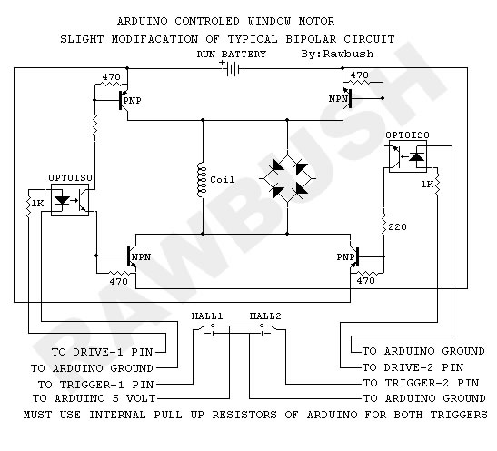
The variables: "threshold" and "current" are the only changes you need to make to tune your circuit. I recommend monitoring the temperature of the transistor carefully. If it is too hot bring the "current" variable to a lower number adjusting until it stays at room temperature.
If the trigger coil is not sensitive enough to trigger the
transistor ON, bring the "threshold" variable to a lower number. As the
motor speeds up you can adjust "threshold" variable lower to fine tune
and also the same with current. Fine tune to a lower "current" variable
when speed stabilizes. You may have to give a nice kick start (rpms) to
start the motor when fine tuned.

Click on image to enlarge.
The Arduino code for my freeduino micro-controller
...written for easy understanding of how it works!
similiar to a PWM but using the delayMicroseconds() to manipulate the trigger and discharging.
Note: Battery supply for the micro-controller is not shown in the drawings and schematics.
I use 3 AA (4.5volts) batteries and optional USB power from laptop that supplies 5.00volts to run the microcontroller
for the triggering and discharging of the Bedini circuit.
Other experimentors researching this concept:
1. Selfonlypath (Youtube)
- http://www.youtube.com/user/selfonlypath
2. Rawbush (Youtube)
- http://www.youtube.com/user/Rawbush
RAWBUSH's Arduino micro-controller running Bi-polar Window Motor
MAllen7424's 3-coil Monopole Pulse Motor/ Generator Animated Schematic
"Click Animation speeds below for a more detailed image
...Be patient for animations to load."
Animation Speed : Fast 24fps |
Medium 12fps (playing...) | Slow 4fps
The above animation I made as a collective idea for a Pulse Motor/High Voltage Generator. This animated document and idea is copyrighted by me. This circuitry and the geometry of motor/ generator is easily scalable in size and output voltage. Referenced from experimentation with my 12 pole and from John Bedini's patents and others. My gift to humanity can only be my love and knowledge for what has been givin to us.
If you notice 4 passes per cycle charging capacitors before the discharge.
If you have not studied John Bedini Pulse Charger Patents, then you will not understand this circuit.
Who needs solar panels or windmills? They are just trying to confiscate acres of land for the harvesting of energy for a profit that is very expensive for the consumer and definately not 21st century.
Our creator wanted us to be self efficient for the evolution of man (not slaves to the bankers & monetary policy) We are created as his equal, making you the sons & daughters of man. We must acknowledge that we are creditors in the realm of commerce. The lust for power & money (debt) has you believe that you posses real substance when in fact is spiralling out of control debt.
The above
Kromrey Generator animation I made in reference to John Bedini information. This animated document is copyrighted by me.
The above No-Load Generator animation I made in reference to
Jong-Sok An patent US 6,208,061 B1 from March 27, 2001. This animated
document is copyrighted by me.
Please leave me some feedback. I seem to be the only one scaling the Bedini motor this large in the public domain.
Comment Below
Update: My talkback application quit because of compatibility, I have upgraded to wordpress, please bear with me in this update.
[ Home ]
Your Ip Address = 37.102.239.188 ----- Visitors: 87616.